Scan to BIM — Revit Models from Laser Scanning Data
Scan to BIM converts point cloud data from laser scanning carried out for survey and engineering purposes into intelligent Revit models — geometry that design teams, BIM coordinators, and engineers can coordinate from. Sky Scan Surveys provides scan to BIM services across the UK, delivering issued models at agreed LOD levels with version control, deviation reporting, and coordination-ready outputs in Revit, IFC, and DWG.
What Is Scan to BIM?
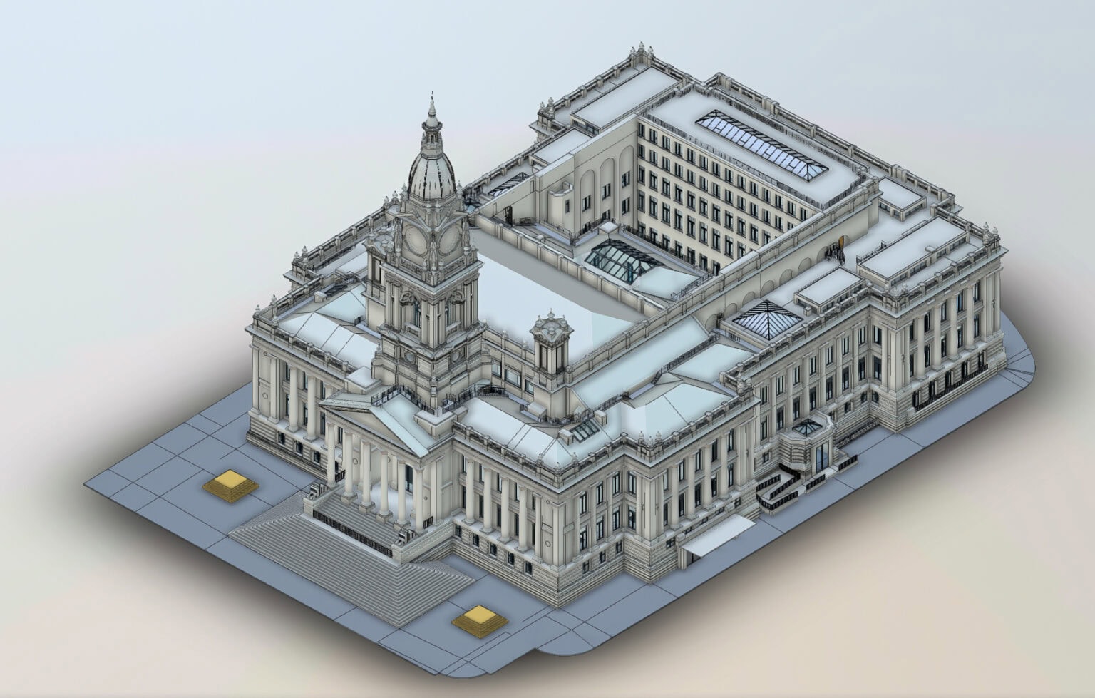
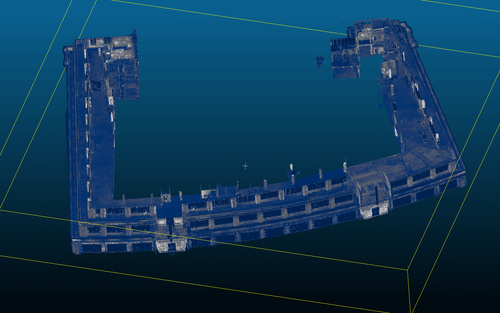
Scan to BIM is the process of converting raw point cloud data — captured by terrestrial laser scanners, mobile mapping, or drone-mounted LiDAR — into a structured 3D model in Revit. The model represents existing conditions: walls, floors, ceilings, structural elements, and MEP services, modelled to an agreed Level of Detail.
A point cloud on its own is a reference dataset with no object intelligence. Scan to BIM adds that intelligence: categorising elements, applying Revit families, structuring by discipline (architectural, structural, MEP), and delivering a model that integrates into the project’s Common Data Environment. The intended use determines the LOD, the disciplines modelled, and the QA requirements.
Benefits of Scan to BIM
Accurate existing conditions
design teams work from measured reality rather than assumptions or outdated drawings
Clash detection
federate MEP, structural, and architectural models to check for spatial conflicts before construction
Reduced RFIs
fewer unknowns in the design model means fewer queries on site
Version-controlled deliverables
issued models carry revision numbers and change logs, so coordination teams always know which version is current
Single-source data
when the same team scans and models, there is no translation gap between surveyor and BIM technician
Where existing drawings are available, scan to BIM validates or replaces them with measured data. Where no drawings exist, it provides the baseline for design to proceed.
Technology, Accuracy & QA
Software and accuracy depend on the deliverable scope:
| Revit | primary modelling environment for architectural, structural, and MEP disciplines |
|---|---|
| Autodesk ReCap / Cyclone | for point cloud registration, cleaning, and QA |
| Navisworks | for federated model review and clash detection, where required |
| Solibri / BIM Collab | for model checking and issue tracking on ISO 19650-compliant projects |
Typical modelling accuracy is ±5–15mm from the registered point cloud, subject to scan density and element complexity. Deviation reports are issued with every delivery — where elements fall outside tolerance, they are flagged in the issue log.
Models are structured to ISO 19650 naming conventions where required. File naming, status codes, and suitability classifications are applied to issued deliverables.
Applications & Use Cases
- Refurbishment and retrofit — creating an accurate existing-conditions model before design changes begin
- Heritage and listed buildings — capturing geometry for conservation planning where as-built drawings do not exist
- MEP coordination — modelling existing services to enable clash-free design of new installations
- Construction verification — comparing as-built scan data against the design model to identify deviations
- Facilities management — providing an intelligent model for ongoing asset management and maintenance planning
Not suitable where the required output is a simple floor plan or 2D drawing only — in those cases, CAD services or a measured building survey may be more appropriate.
Project Evidence
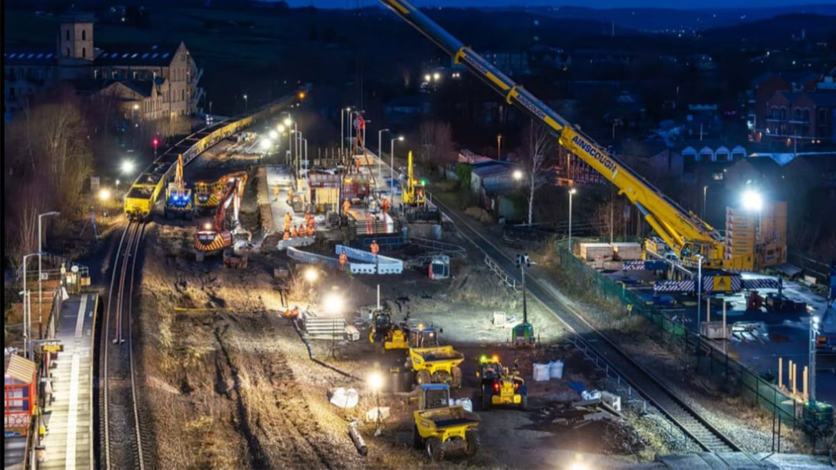
Mirfield Station, West Yorkshire
Client: Tier 1 civil engineering contractor | Sector: Rail / Transport
Context: A major rail contractor required accurate as-built survey data of Mirfield Station to support design coordination and construction works.
Restricted site access and operational railway constraints meant survey capture needed to be completed quickly and integrated directly into the BIM workflow.
- Georeferenced orthomosaic
- DWG drawings referenced to project control network
- TIN surface model
- Dense point cloud
- All outputs transformed to TPENN16 coordinate system for Network Rail compatibility
- Registered point cloud dataset
- BIM-ready Revit model
- Clash detection support data
- DWG reference drawings
- Coordinate transformation to TPENN16
- Sub-2cm accuracy achieved
- Deliverables integrated into project design workflow
- Data compatible with Network Rail coordinate system
Method: Laser scanning + drone photogrammetry | Point cloud registration | BIM model generation | TPENN16 coordinate transformation
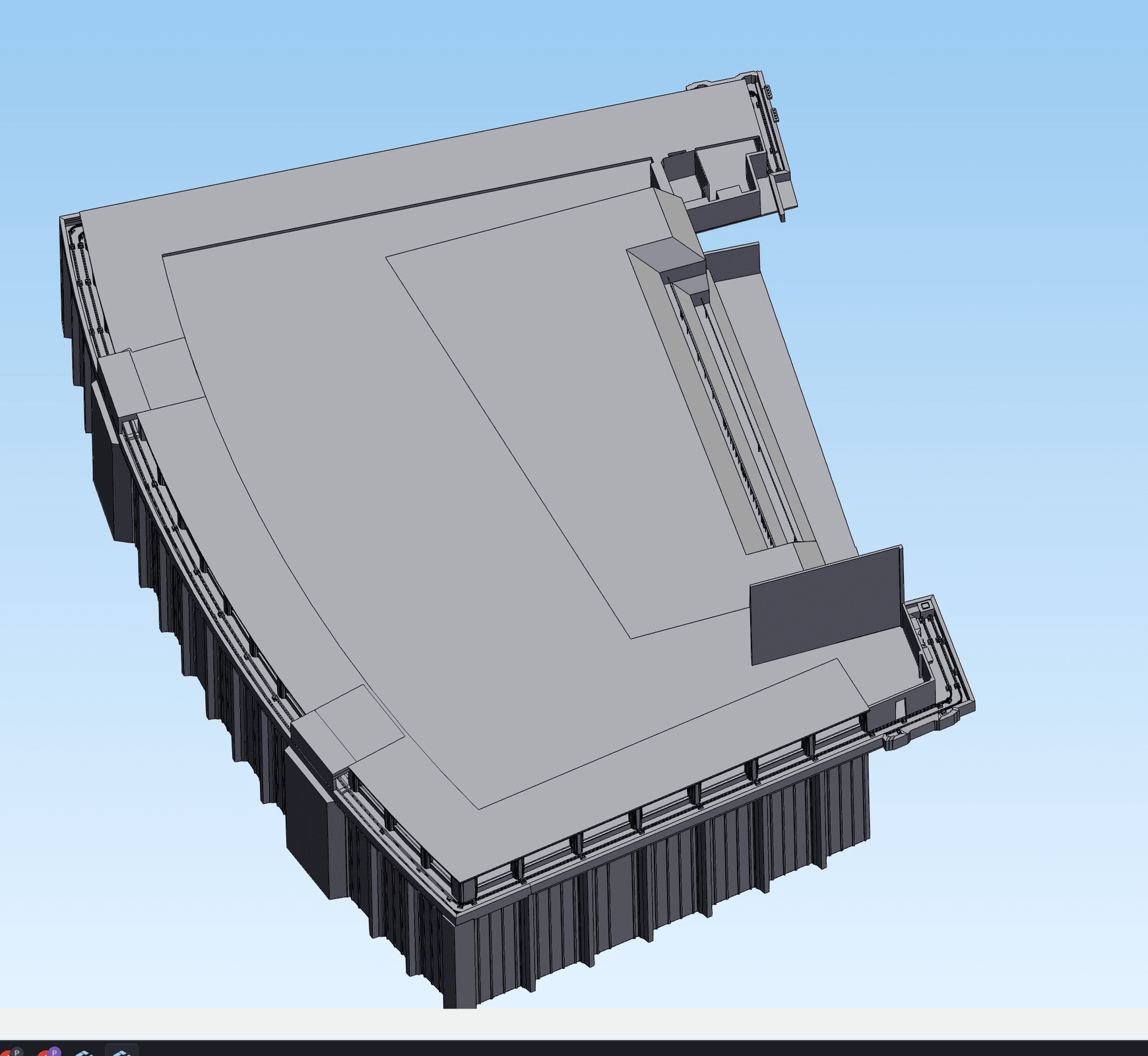
Barkers of Kensington, London
Client: A specialist access solutions company | Sector: Commercial, Manufacturing
Context: An engineering company needed terrestrial laser scan data of a building facade converted into a manufacturing-grade 3D solid model — so their fabricators could design and produce bespoke access equipment to exact dimensions. The manufacturers needed accuracy down to individual 20mm diameter studs and plinth positions.
- Registered TLS point cloud (E57)
- STEP solid model built from scratch for SolidWorks
- Individual studs modelled at 20mm diameter with plinth positions
- Transparent documentation of areas where reduced point density limited feature extraction
- Final STEP model accepted and sent directly to manufacturers for fabrication
- 4+ revision cycles completed to meet engineering specification
Stud diameters corrected from 40mm to 20mm per client feedback during iterative QA
Method: Terrestrial laser scanning → STEP solid model conversion | Iterative QA with manufacturer feedback
"The model is great. The manufacturers are currently looking over it."
- Design Manager, specialist access solutions company
Our Scan to BIM Process
Scope and LOD agreement
We confirm which disciplines are required (architectural, structural, MEP), the Level of Detail (LOD 200 for coordination, LOD 300 for design development, LOD 400 where fabrication-level geometry is needed), the coordinate system, and the model purpose.
Laser scanning
Point cloud data is captured on site using terrestrial scanners, with control established to OSGB36 or project grid. Scan density and coverage are matched to the agreed LOD. View LiDAR Surveys →
Point cloud registration and QA
Scans are registered, cleaned, and checked for coverage gaps, alignment drift, and noise. Registration reports are issued with deviation values.
Revit modelling
Elements are modelled from the registered point cloud to the agreed LOD using Revit families, categorised by discipline. Where elements are obscured or inaccessible, they are flagged — not guessed.
QA and deviation check
The model is checked against the point cloud. Deviation maps highlight areas exceeding tolerance. Discrepancies are documented in an issue log for client review.
Issue and revision control
The model is issued with a revision number, change log, and coordinate reference. Updates from new data or design changes are revision-tracked.
Pricing & Service Options
Scan to BIM costs depend on the building area, number of disciplines, LOD requirement, and whether scanning is included or data is provided by a third party.
| Service | Typical Starting From |
|---|---|
| Single-discipline model (geometric only, LOD 200) | £1,499+ |
| Design-ready model (architectural + structural, LOD 300) | £1,799+ |
| MEP modelling (add to any LOD level) | +£500 |
| LOD 400 fabrication-level modelling | Quote required |
| Model update / revision from new scan data | £499+ |
| Point cloud only (no modelling) | £799+ |
Most projects fall into the LOD 200–300 range for coordination and design development. Pricing is also influenced by building complexity, ceiling height, access constraints, and turnaround requirements. All pricing includes QA verification and deviation reporting.
Deliverables & File Formats
Standard deliverables from a scan to BIM project:
| Revit model (.rvt) | the primary BIM deliverable, structured by discipline with Revit families |
|---|---|
| IFC export (.ifc) | for coordination in open BIM environments (Solibri, BIM Collab, Trimble Connect) |
| DWG extracts | 2D plans, sections, and elevations extracted from the Revit model for teams working in AutoCAD. View CAD Services → |
| Point cloud (.e57 / .rcp) | the registered, cleaned source data for client reference |
| Deviation reports | visual overlay showing model-to-cloud alignment with colour-coded tolerance bands |
| Sheet sets and view sets | issued plan, section, and elevation views from the Revit model, version-controlled |
All deliverables include coordinate system reference, revision number, and limitations noting any restricted access or obscured elements.
Why Choose Sky Scan Surveys
Scan and model under one roof
The same team captures the point cloud and produces the BIM model, reducing handoff errors.
LOD-specific delivery
Models built to the agreed Level of Detail to suit the project requirements.
Deviation reporting included
Issued models include deviation checks against the source point cloud.
ISO 19650-compatible delivery
Information structures and naming conventions can follow ISO 19650 where required.
Verified capture accuracy
Point cloud data captured using high-accuracy laser scanning and registered to survey control.
Trusted By


Frequently Asked Questions
What Level of Detail (LOD) do you model to?
We model to LOD 200, 300, or 400 depending on the project requirement. LOD 200 provides approximate geometry suitable for coordination and spatial planning. LOD 300 includes accurate dimensions and positions for design development. LOD 400 is fabrication-level detail — typically required only for specific elements. The LOD is confirmed at the scoping stage.
How accurate is the Revit model compared to the point cloud?
Typical modelling accuracy is ±5–15mm from the registered point cloud, depending on scan density and element complexity. Every model is issued with a deviation report showing where geometry aligns within tolerance and where exceptions exist. We do not guarantee accuracy for elements that are obscured or inaccessible during scanning.
Can you model from our existing point cloud data?
Yes, subject to a data quality review. We check registration, density, coverage, and coordinate reference before quoting. Where data gaps exist, we flag them — either a supplementary scan or a noted limitation in the model.
How long does a scan to BIM project take?
Scanning typically takes 1–3 days on site. Modelling and QA take 10–15 working days for a standard multi-discipline model. Rush turnarounds available for critical path projects, subject to resource.
What file formats do you deliver?
Standard deliverables include Revit (.rvt), IFC (.ifc), DWG extracts, registered point cloud (.e57/.rcp), and deviation reports. Sheet sets with plans, sections, and elevations are issued from the Revit model. All files include coordinate system metadata and revision numbers.