
CAD Services — Clean DWG Drawings, Plans and Sections
CAD services turn raw survey data into usable drawings — plans, sections, elevations, and models that engineers and designers can actually work from. Sky Scan Surveys provides CAD drawing production across the UK, working from our own survey data or from third-party datasets, with outputs delivered to client CAD standards and version-controlled throughout.
What Are CAD Services?
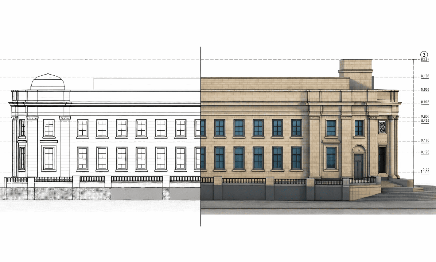
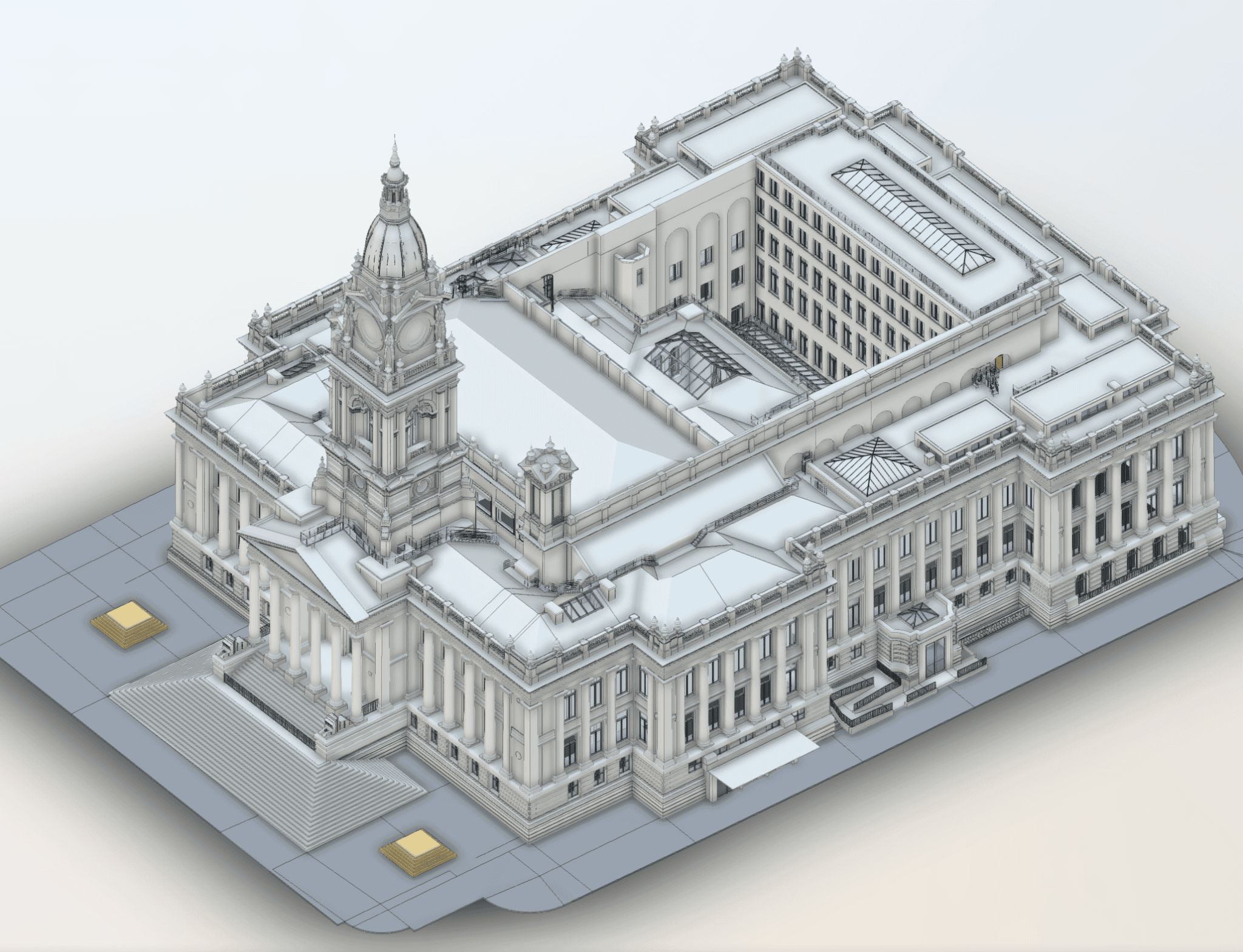
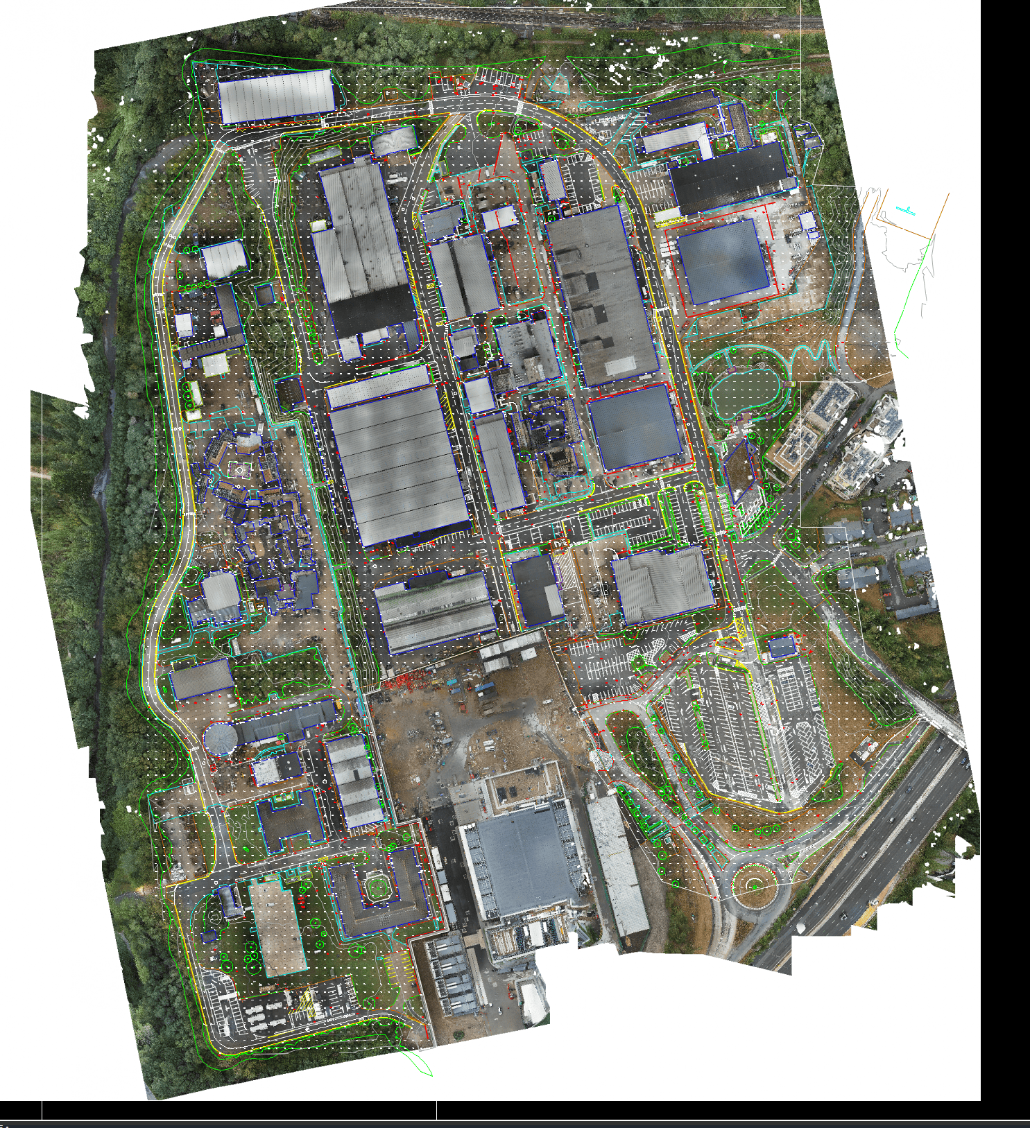
CAD services cover the production of technical drawings from survey data. This includes site plans, topographic plans, cross-sections, long sections, elevations, detail drawings, and 3D models — produced in industry-standard formats including DWG, DXF, and Revit.
The scope depends on what the drawings need to support. A setting-out drawing for a groundworks contractor has different requirements to a site plan for planning — different detail levels, layer structures, and annotation standards. We confirm the intended use before starting production.
Key deliverables include:
- Site plans with contours, spot heights, and feature detail
- Cross-sections and long sections for engineering design
- Version-controlled drawing sets with revision tracking
All outputs are referenced to the source survey data and issued with coordinate system metadata. Where drawings are produced from third-party data, we note the source and any limitations in the title block.
Get an Instant Drone Survey Quote
Drone survey prices start from £349 for roof inspections, £599 for topographic surveys, £1,199 for LiDAR and measured building surveys, and £1,499 for Scan to BIM.
Prices shown are guide estimates. Final proposals confirmed after reviewing site access, deliverables, and required accuracy. CAA licensed. £1M PI. £5M public liability.
Benefits of CAD Services
Outsourcing drawing production has practical advantages:
Consistent standards
drawings produced to your CAD standards (layer naming, line types, title blocks, annotation styles) so they integrate with your existing project files without manual rework
Faster turnaround
dedicated drawing production frees your survey or design team for the next project
Version control
every drawing is issued with a revision number and change log, so you always know which version is current and what changed between issues
Format flexibility
outputs in DWG, DXF, PDF, Revit, and other formats as required, from the same source data
Single-source accountability
when the same company captures the survey data and produces the drawings, there is no translation loss between surveyor and draughtsman
Drawings are issued with a revision schedule and are subject to client sign-off procedures where required.
Technology & Software
The software and approach depends on what the output needs to be and what the client’s design environment requires:
| AutoCAD | for 2D plans, sections, and elevations in DWG/DXF format. This covers the majority of survey drawing production |
|---|---|
| Revit | for BIM-ready deliverables where the design team works in a Revit environment. Survey data is structured into Revit families and categories. View Scan to BIM → |
| Civil 3D | for infrastructure and highway design deliverables requiring surface models, alignments, and corridor sections |
| Point cloud processing | for extracting CAD linework from laser scan or photogrammetric point cloud data. View LiDAR Surveys → |
| PDF to CAD conversion | for digitising existing paper or PDF drawings into editable CAD format |
Where clients use specialist software (MicroStation, ArchiCAD, or sector-specific platforms), we export in compatible formats. File format is confirmed at briefing to avoid conversion issues downstream.
Applications & Use Cases
CAD drawing production applies wherever survey data needs to become a finished, usable drawing:
- Planning submissions — site plans and topographic plans formatted for local authority requirements
- Construction setting out — drawings with grid references, levels, and dimensional control for groundworks contractors
- Engineering design input — cross-sections, long sections, and surface models as the base layer for civil, structural, or drainage design
- As-built documentation — record drawings from completion survey data, version-controlled against the original design
- Drawing revisions — updating existing CAD drawings with new survey data, client markup, or design changes, with full revision tracking
- Legacy drawing digitisation — converting paper drawings, scanned PDFs, or outdated file formats into current, editable CAD files
Primary clients include design managers, project managers, civil engineers, and surveying consultants who need finished drawings rather than raw survey data.
Project Evidence
Scan-to-STEP Conversion, London
Client: A specialist access solutions company | Sector: Manufacturing, Engineering
Context: A specialist engineering company had terrestrial laser scan data of a building facade but needed it converted into a SolidWorks-compatible STEP file for their manufacturers. Raw point cloud data can’t be imported into manufacturing CAD software — the gap between “survey data” and “something a fabricator can actually use” is where most projects stall.
- STEP (.stp) solid model built from registered TLS data
- Individual architectural features modelled to manufacturing tolerance
- E57 point cloud source file
- Clear documentation of modelling limitations and assumptions
- STEP file in production use by manufacturers
- 4 revision cycles ensured output matched fabrication tolerances
- Bridged the gap between survey data and manufacturing CAD
Method: TLS point cloud (E57) → STEP solid model | SolidWorks-compatible output | Iterative revision process
The model is great. The manufacturers are currently looking over it."
— Group Engineering Director
Topographic to DWG Delivery, Surrey
Client: A major film production facility | Sector: Film, Media
- Structured Civil3D DWG with client’s layer naming conventions
- Spot elevations, contours, feature codes and boundary data
- All layers organised to match existing project standards
- DWG imported directly into the client’s CAD environment without rework
- No reformatting or layer restructuring required by the design team
- Deliverable matched the exact specification agreed at project scoping
Method: GNSS control network | Total station verification | Aerial survey integration
“The control network and survey data allowed our team to stake out the design accurately and proceed with construction without delays.”
— Senior Project Manager, construction services contractor
Our CAD Services Process
Drawing production follows a structured workflow because errors in CAD output propagate downstream — into setting out, quantities, and design coordination.
Drawing brief
We confirm what drawings are needed, what format, and what CAD standard applies. If you have a client CAD manual or layer naming convention, we work to it. If not, we apply our standard structure and agree it before production starts.
Source data review
The survey data is checked for completeness, coordinate reference, and suitability for the required outputs. Where data gaps exist — for example, a missing elevation at a critical point — we flag it before starting rather than guessing.
Drawing production
Plans, sections, elevations, and models are produced from the source data. Feature coding is applied consistently, contour intervals are set to the agreed specification, and annotation follows the confirmed standard.
Client standard application
Layer naming, line types, title blocks, and dimension styles are formatted to match the client’s CAD environment. Where BIM deliverables are required, data is structured for direct Revit import.
QA check
Drawings are verified against source data. Spot checks on dimensions, levels, and feature positions confirm the output matches the input within tolerance.
Issue and revision control
Drawings are issued with revision numbers, a change log, and coordinate system reference. Revisions from new data or client markup are tracked so the full history is auditable.
Pricing & Service Options
CAD drawing costs depend on the number and complexity of drawings required, the source data format, and the CAD standard to be applied. Standalone drawings and full drawing packages are both available.
| Service | Price Range |
|---|---|
|
Topographic Survey to Civil 3D Surface model, contours, spot elevations, georeferenced site plan — DWG/DXF | £499 – £1,499 |
|
AutoCAD Elevation Drawings Scaled 2D architectural elevations from scan or survey data — DWG and PDF | £249 – £599 |
|
GIS / Shapefile Data Output Georeferenced .shp for planning and environmental use — QGIS, ArcGIS, MapInfo compatible | £349 – £799 |
|
Revit BIM Model — LOD 300 Full geometric model from scan or point cloud data — RVT and IFC output | £799 – £2,499 |
|
Drawing Amendments and Revisions Minor or major revision rounds for existing survey drawings — scope confirmed at briefing | From £149 |
|
Ongoing CAD Support — Retainer Retainer-based draughting for engineering and design teams | Quote required |
Pricing is influenced by whether source data is from our survey or third-party, client CAD standard requirements (custom layer naming, title blocks), and turnaround — standard is 5–10 working days; rush turnarounds are subject to resource availability and may carry a premium. All pricing includes QA verification against source data. Formal quotes issued once the drawing brief and source data are reviewed.
Why Choose Sky Scan Surveys
Survey and CAD production under one roof
The same team that captures survey data produces the drawings.
We work to your CAD standard
Layer naming, line weights, title blocks and drawing registers can match your CAD requirements.
Version-controlled drawing issues
Each drawing issue is revision-tracked with clear change history.
Matched to your design environment
Outputs delivered in DWG, DXF, PDF, Revit or Civil 3D formats as required.
Revision turnarounds within 48 hours
Standard revisions returned quickly for active design programmes.
Trusted By


Frequently Asked Questions
What formats do you deliver CAD drawings in?
Standard formats include DWG, DXF, and PDF. Where clients work in BIM environments, we deliver in Revit (RVT) or IFC format. Civil 3D files are available for infrastructure projects. If your design team uses a specific platform, let us know at the briefing stage — confirming the output format early avoids conversion problems later.
Can you work to our CAD standards?
Yes. If you have a CAD manual specifying layer naming, line types, dimension styles, or title block templates, we apply them. Where no client standard exists, we use our own consistent structure and agree it with you before production begins.
How long does CAD drawing production take?
Turnaround depends on the number and complexity of drawings. A single site plan from clean survey data might take 1–2 working days. A full drawing package with sections, elevations, and detail sheets typically takes 5–10 working days. Rush turnarounds are available for critical path projects, subject to resource and current workload.
Can you update existing drawings with new survey data?
Yes. When new survey data is captured — after a phase of construction, for example — we update the relevant drawings, increment the revision number, and document the changes. The original is retained so the full history is traceable.
Do you produce BIM models from survey data?
Yes, though for complex BIM projects this is typically handled through our dedicated Scan to BIM service, which involves point cloud processing and Revit modelling. For simpler requirements — such as importing survey data into an existing Revit model — CAD production can handle the conversion directly. View Scan to BIM →
Data Accuracy & Limitations
All CAD drawings are produced from source survey data and are only as accurate as the data they derive from. Drawings include coordinate system reference and note the source dataset. CAD outputs do not independently verify source data accuracy — if the survey has limitations, those carry through into the drawings. Where third-party data is used, we note this in the title block and exclude accuracy guarantees for the source.